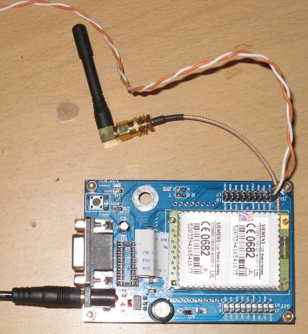
To connect the Siemens phone to your project, a data cable and level shifter was required. This is not the case when you use a GSM module. I bought the Siemens TC35 from ebay. There are 2 version of this board; version 1 and version 3. Version 1 has 2 disadvantages:
- Linear 3.3 Volt power regulator, while the input voltage is 12 Volt. Therefore the power regulator will become quite hot and the board consumes a lot of power.
- There is no room between the power connector and the rs232 connector. You cannot connect both a rs232 cable and a power connector (I do not use the rs232 connector, but is a design error nonetheless).\
 Version 3 is a better choice. It is slightly more expensive, has a better regulated and switched power supply. Moreover the schematic of version 3 is available on the internet, which is quite nice. Furthermore it has jumpers to change some settings, a status LED for incoming calls and a better protections against adapters with the wrong polarity. When I received my TC35 board, it was dead on arrival. I found out that the diode that was put across the input terminals was broken, resulting in a short circuit. So I removed it from the board. The board has a rs232 output (with a max232), but also a header with TTL outputs, called TXD0 and RXD0. Moreover, several headers for the power connections are on the board. To connect the board to an arduino (or other microcontroller), it is most easiest to run the microcontroller on 3.3 Volt. My arduino demealove can do this using a jumper. Because the Siemens GSM module works on 3.3. Volt, the logic levels should be between 0 and 3.3. Volt as well. Connect the UART from the microcontroller to the TXD0 and RXD0 of the GSM board and remove the max232 from the board (in case of version 1) or remove the jumpers (version 3). If the max232 is connected, I received wrong signals due to the “load” of the max232. <afbeelding connected to arduino> In case of an Arduino Uno or demealove, it is most easiest to use a software serial port, so you can use the hardware serial port for communication with a computer. The baudrate is 9600, with 1 stopbit and no flow control. A demo program can be found at http://denhart.dk/2012/01/siemens-tc35-gsm-module-arduino)
Get phone number from incoming call
The Arduino code below is an example that retreives the phone number of an incoming call. In the picture below, the terminal with and without all data send by the TC35 is shown. 
//in case of a \r\nRING\r\n, detect the phonenumber and send this to the Serial terminal of the computer
//uses RX/TX of arduino for PC communication
//uses software serial port for rx/td to TC35 board.
//all received data from the phone is displayed in the terminal

#include <SoftwareSerial.h>
SoftwareSerial gsmSerial(2,3);

char receivedByte;
int index;
char buffer[100];
int flagRING=0;
int numberFlag=0;
int j;
int telStart,telEnd;
String phoneNumber;
char gsm_char;

void setup(){
  Serial.begin(9600);
  gsmSerial.begin(9600);

  Serial.println("\r\nCommunication started\r\n");

  //start communication with GSM
  gsmSerial.print("AT\r");
  delay(400);
  //PIN not necessary
  gsmSerial.print("AT+CPIN=0000\r");
  delay(400);
//Enable number of calling phone, without this command
//only \r\nRING\r\n is receivied in case of an incoming call
  gsmSerial.print("AT+CLIP=1\r");
  delay(400);
}

void loop(){

  if(gsmSerial.available()>0){

   	receivedByte = gsmSerial.read();
        //Serial.print(receivedByte);
        buffer[index]=receivedByte;

        if(flagRING==0)
        {
  	    if(receivedByte == '\n'){
              index =0;
              buffer[index]=NULL;
              //Serial.println("newline received");
            }
            else{
              index++;

              if(index==4  && buffer[3]=='G' && buffer[2]=='N' && buffer[1]=='I' && buffer[0]=='R'){
                Serial.println("There is an incoming call\r\n");
                //search for telephone string

                flagRING=1;
              }
            }
         }
        //if RING
        if(flagRING==1){

            if(receivedByte==':'){    //first number of telephone
                telStart=index+2;           //first number (that is the the second character after ':' (first character is a space)
            }
            if(receivedByte==','){
                //last number of telephone number
                numberFlag=1;
                telEnd=index;  //remove comma
            }
            index++;

        }

   }
   if(numberFlag==1){
     for(j=telStart;j<telEnd;j++){
         phoneNumber=phoneNumber+buffer[j];


     }
      Serial.println("\r\nThe calling phone number is:");
      Serial.println(phoneNumber);
      Serial.print("\r\n");
      numberFlag=0;
      flagRING=0;
      phoneNumber=0;
      index=0;
      buffer[index]=NULL;
   }

 //when the character c is received from the terminal of the computer
 //call a number (feature just for testing TC35 board)
  if(Serial.available() >0){
    gsm_char=Serial.read();
     if(gsm_char=='c')
     {
       gsmSerial.write("ATD+31619027454;\r");
     }
  }

}
Send SMS in text mode
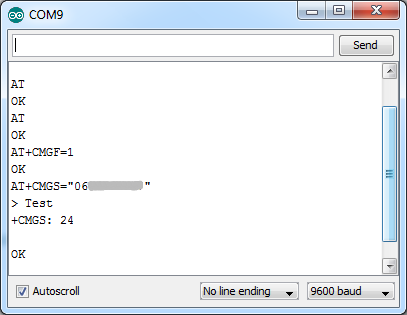
The example below shows how you can send a SMS in text mode. When the character s is received from the Serial terminal, a SMS is send. Al received data from the TC35 board is send directly to the serial terminal of the computer.
//send an SMS using a TC35 gsm module
//some more AT commands can be given as well (ATD,AT,SMSC)
//communication between tc35-arduino using software serial port
//RXD0 TC35->arduino pin 2
//TXD0 TC35->arduino pin 3
//dont forget to connect the ground
//PIN was disabled

#include <SoftwareSerial.h>
SoftwareSerial gsmSerial(2,3);

char gsm_char,gsm_char_send;

String cellContent=""; //string we're sending
String ctlZ="\x1A"; //the code for Ctrl-Z
String SMScontent="Test"; //the actual SMS message

void setup(){
 Serial.begin(9600);
 gsmSerial.begin(9600);

 Serial.println("\r\nCommunication started\r\n");

 //start communication with GSM
 gsmSerial.print("AT\r");
 delay(400);

}
void loop(){

 if(gsmSerial.available()>0){
 gsm_char_send=gsmSerial.read();
 Serial.print(gsm_char_send);
 }

 //when the character c is received from the terminal of the computer
 //call a number (feature just for testing TC35 board)
 if(Serial.available() >0){
 gsm_char=Serial.read();

 if(gsm_char=='c')
 {
 //call number
 gsmSerial.write("ATD+31619027454;\r");
 }
 else
 if(gsm_char=='s')
 {
 //add message to the CellContent string
 cellContent+=SMScontent;
 //add the Crtl-Z character
 cellContent+=ctlZ;

 //send SMS in text mode
 gsmSerial.print("AT+CMGF=1\r");
 delay(400);

 sendSMS();

 }
 else if(gsm_char=='t')
 {
 gsmSerial.print("AT\r");
 delay(400);
 }
 else if(gsm_char=='d'){
 //set SMSC number (if needed)
 gsmSerial.print("AT+CSCA=\"+31626000230\"\r");
 delay(100);
 }

 }
}

void sendSMS(){

 gsmSerial.println("AT+CMGS=\"0619027454\""); //AT command to send SMS
 delay(500); //the length of this delay is very important. 400 is too low
 gsmSerial.print(cellContent); //Print the message
 delay(15);
}


9 thoughts on “Siemens TC35 GSM board”