Shunt and series regulators
There are 2 possible methods to make a (lineair) adjustable power supply: a shunt regulator and a series regulator. Because the shunt regulator has many disadvantages over a series regulator, it will not be discussed on this website. However, you will sometimes find this type if you use e.g. a voltage reference IC.
Types of series regulators
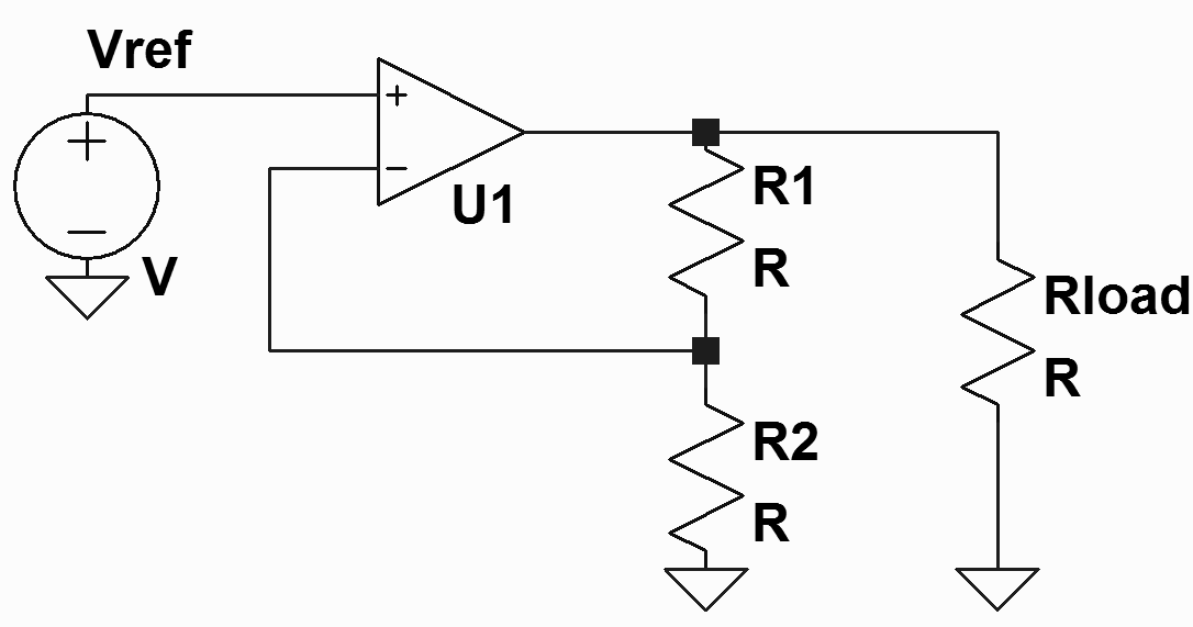
Most of the times, 2 different ways are used to make a series regulator. The simplest method is shown in the Figure below:
The opamp is used as non-inverting amplifier. The voltage at + and- input will be equal, so the output voltage is dependent on the reference voltage, R1 and R2:
Vout=(1+R1/R2)*Vref
This topology is used in e.g. the 78xx regulators
A disadvantage is the resistor devider in the feedback loop:
- If the output voltage suddenly changes, the resulting voltage difference is first attenuated by the feedback resistors and then adjusted.
- Noise from the reference voltage will be seen amplified at the output.
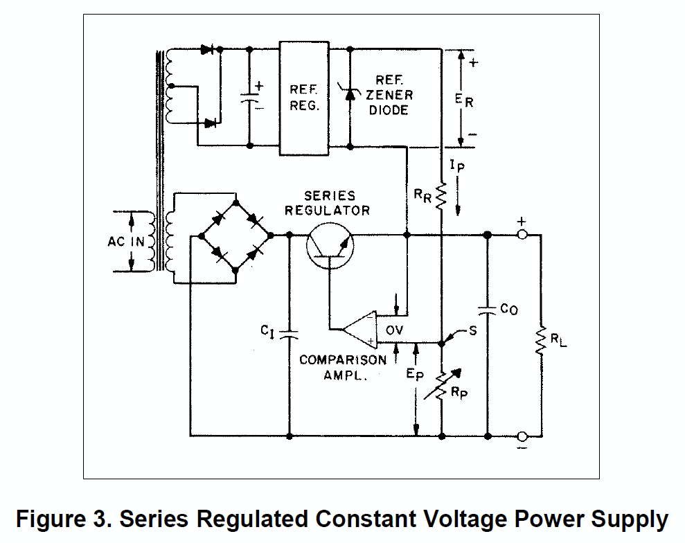
In professional power supplies of e.g. Delta and Agilent, therefore another topology is used with unity (1x) gain.
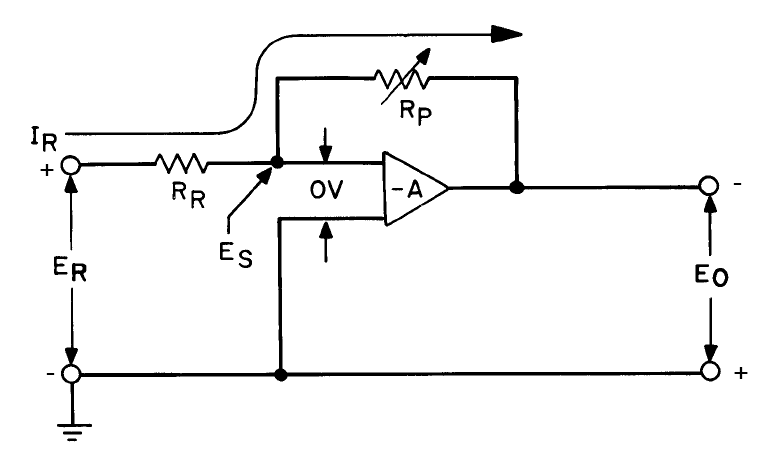
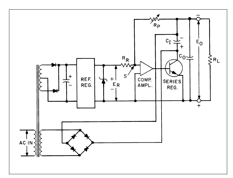
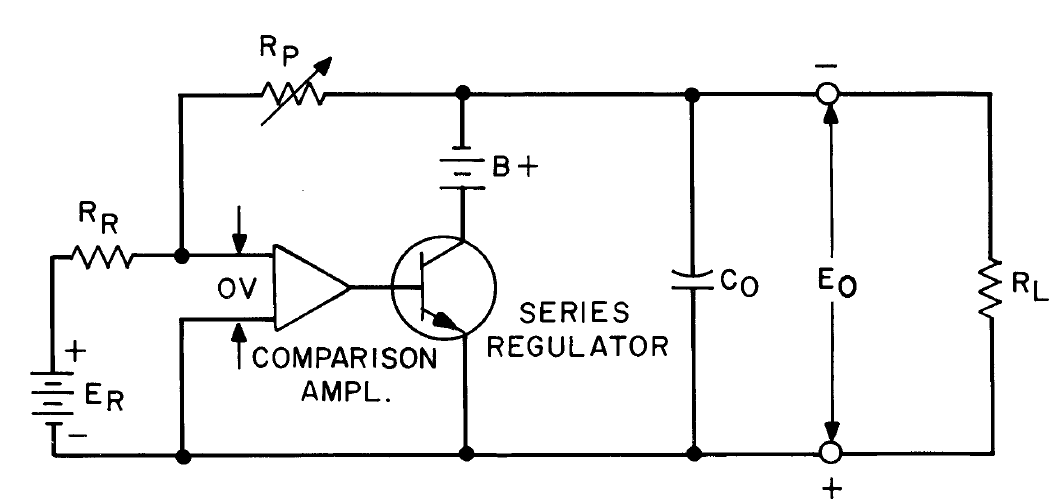
The opamp has now unity gain. Therefore, the + and – input will be ate the same voltage. The ground of the voltage reference is now connected to the positive output, providing a constant current through RR. The voltage across Rp therefore determines the output voltage. A constant current ER/RR determines the voltage across Rp. Because the inputs of the opamps have a very high input impedance, all this current will flow through Rp, which sets the output voltage. If Rp=0 Ohm, the output will be 0V.
The power supply of the opamp can be made from the safe transformer as the reference voltage. The output voltage is thus not limited by the voltage limitations of the opamps. There are always 2 transformers required for this topology.
The following figures will possibly make the theory of operation more clear:
Most of the pictures are from the Agilent AN90B application note (tip!).
Current control
More about current control can be found in the application note 90B, or in the following links/schematics:
- Delta Elektronica Zierikzee E015-2 schematic
- ELV Universelle netzplatine
- Elektor 82 power supply
- HP 6200B schematic
- HP/agilent HP-E3617A
- Agilent Agilent_E3631
- Everyday practical electronics 1-2002
What to build? What’s best?
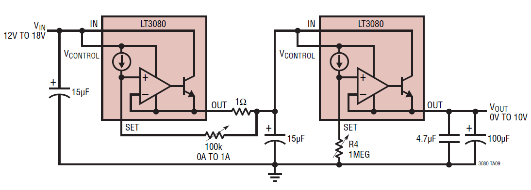
If you want to make a very simple power supply without adjustable current limit, I would advise to use an IC like the LM723 or LT3080. The LM723 is quite old, but very cheap. The LT3080 needs only a potentiometer and 2 capactitors to work.
In you want current control as well and you have a small budget, I’d look at this CA3140 power supply. Only 1 transformer is required for that design and the CA3140 is a cheap opamp.
If your budget is larger, you can look at an LT3080 power supply or one of the many examples that were provided on this page under the heading current control.

